House on Gakuenodori
Dirt floor as an environmental control system
 |
|||
| When the dirt floor is open © Koji Okamoto |
|||
 |
 |
 |
 |
In summer and the intermediate seasons, the external fittings and the fittings provided in the dirt floor are open to facilitate ventilation and drafts, and passive cooling is performed by making use of the thermal capacity of the dirt floor. In active mode at midsummer, the boundary between the dirt floor and the rooms is closed, and only the room areas are air-conditioned (the air conditioner is controllable in each room).
Winter
When the solar irradiance is high, the ceiling fan clears vertical temperature distribution and, at the same time, facilitates heat storage in the dirt floor. When the solar irradiance is low, the dirt floor functions to provide buffer space between the inside and the outside by closing the fittings there. At night, the rooms are warmed by heat released from the heat storage space. In active mode, the boundary between the dirt floor and the rooms is closed up to warm only the room areas (the air conditioner is controllable in each room).
Keeping the indoor environment comfortable
 |
|||
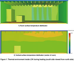
| Figure 1: Thermal environment inside LDK during heating (south side viewed from north side) | |||
 |
 |
 |
 |
Each room faces the open dirt floor space. If necessary, passive environmental control is available selectively and effectively by comprehensively using the dirt floor. However, the opening ratio of the dirt floor space is large, and there was a concern about heat loss in winter and an increase in solar heat load in summer. For this reason, heat insulating sashes (pair glass) and sufficient thermal insulating materials (roof: HGW16K/200 mm, wall: HGW16K/100 mm, floor: Styrofoam/50 mm) are used to fulfill the next-generation energy-saving standard (Q value = 2.66 W/m²・K, μ value = 0.062 [-]). In addition, airtightness performance is improved by a foundation thermal insulation method, and an air type underfloor air conditioning system (a duct type air conditioner is placed under the floor) was adopted, which uses the underfloor space as a heat conveyance passage. To verify the performance of this system and determine its specifications, we conducted CFD (computational fluid dynamics) simulations. and confirmed that a comfortable indoor thermal environment was achieved. Figures 1 and 2 show the analysis results during heating and during cooling, respectively. During heating, no vertical temperature distribution appears, and a uniform thermal environment is formed. During cooling, only the room areas below the air inlet are air conditioned (layered air conditioning).
With regard to underfloor cooling, there was a concern about an increase in the difference in temperature between the upper and lower areas and discomfort. We, therefore, measured the
indoor thermal environment in August 2008. Figures 3 and 4 show images during cooling and heating, respectively. In the daytime, the outside air temperature reaches about 30°C and
the solar irradiance rises up to about 1000 W/m². By adjusting the cooling diffusion conditions, the difference in temperature between the upper and lower areas can be reduced to 3°C
or below, ensuring a comfortable indoor environment.
Previous Building |
 |
 |
 |
 |
 |
 Next Building Next Building |
CASBEE is a method for rating the environmental performance of buildings using Building Environmental Efficiency (BEE) as an indicator, which is based on the results of separate scores obtained for Q-1~Q-3 (Quality) and LR-1~LR-3 (Load Reduction).


 | Copyright © 2008 Institute for Building Environment and Energy Conservation, All Rights Reserved.