Sakai Gas Building
Air conditioning system combining natural ventilation and ceiling fans
 |
|||
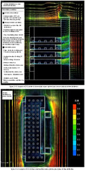
| Figure A1: CFD of natural ventilation | |||
 |
 |
||
An effective amount of natural ventilation is ensured by minimizing the resistance in the ventilation route. Additionally, since there is a major road in front of the site, outside air is not introduced directly through windows. Instead, it is slowed down by a chamber and then introduced into and passed through an underfloor trench at low velocity to prevent the ingression of noise and dust into rooms. As a result of CFD analyses, the air velocity in the rooms on the typical floor was about 0.2 m/s, and that in the staircase was 0.5 to 0.7 m/s.
Air conditioning system combining natural ventilation and ceiling fans
ceiling fan
 |
|||
| Figure B1: Air velocity distribution on plane at a height of 1.1 meters from the floor surface of the typical floor with the ceiling fans in operation | |||
 |
 |
||
The results of the questionnaire given to residents conducted during air conditioning with the ceiling fans revealed that 86% of residents had a sense of coolness in connection with the thermal environment of their rooms, both visually and in terms of air flow.
Air conditioning system combining natural ventilation and ceiling fans
construction and operation performance of control system
 |
|||
| Figure C1: Ratio of operation modes for cooling period from April through November 2004 | |||
 |
 |
 |
|
The results of room temperature variation measurement in the intermediate season showed that various air conditioning modes were selected in air conditioning hours, and the room temperature did not remain constant as with standard air conditioning systems but varied within a comfortable range. We confirmed that air conditioning modes were selected according to outside air conditions and while internal load variations were accepted, and the thermal environment inside the office space was controlled using as little energy as possible and within a specific allowance.
Use of exhaust heat for a cascade by micro gas turbine cogeneration
 |
|||
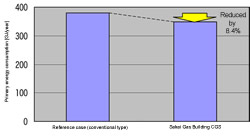
| Figure D1: CGS Energy saving rate | |||
 |
|||
Exhaust heat is recovered by an exhaust gas input type cold/warm water gas system and then transformed into warm water by an exhaust gas heat exchanger. Exhaust heat recovery is performed by a desiccant air conditioning system during the cooling period, by a warm water heat exchanger for heaters during the heating period, and by a heat exchanger for hot water supply to hot water supply loads throughout the year using exhaust heat for a cascade.The energy saving rate throughout the year was 8.4%.
Previous Building |
 |
 |
 |
 |
 |
 Next Building Next Building |
CASBEE is a method for rating the environmental performance of buildings using Building Environmental Efficiency (BEE) as an indicator, which is based on the results of separate scores obtained for Q-1~Q-3 (Quality) and LR-1~LR-3 (Load Reduction).


 | Copyright © 2008 Institute for Building Environment and Energy Conservation, All Rights Reserved.